Team 204: Solar Signal

Solar Garden Weather Station
Team Members:
Brennan Potter, Gavin Nielsen, Jeremiah Herrera, Jacob Cousins
Preperation Date: 4/18/2024
Arizona State University
EGR 314
Professor Travis Kelly
Mission Statement:
Our mission is to introduce an innovative garden weather station that redefines sustainable gardening. Leveraging the synergy of solar tracking technology and environmental sensors, our system meticulously monitors and responds to garden conditions, optimizing solar energy utilization for prolonged operation. With onboard temperature, light, and soil moisture sensors, coupled with a motor-controlled solar panel, we are committed to providing gardeners with a reliable, eco-friendly solution, empowering them to nurture their gardens efficiently and sustainably.
Introduction:
There are many weather station devices on the market today, our teams goal is to stand out and deliver a product of unrivaled quality. The main components behind this product are the ability to track various aspects about the outside weather and soil moisture levels and relay that to the user to allow them to make the best decisions possible when maintaining a garden. The product will also have an automatically adjustable solar panel that tracks the sun and can deliver power to various other devices of the user’s choosing. Through the use of smart manufacturing techniques we aim to make this device affordable while having it be robust in its functions. Lastly, its ease of use should rival or beat that of other market competitors so that any person, regardless of their technical proficiency, can operate our product to get the most out of it.
Table of Contents
- Team Organization
- User Needs
- Design Ideation
- Selected Design
- Block Diagram
- Component Selection
- Microcontroller Selection
- Hardware Implementationl
- Software Implementation
- System Verification
- Lessons Learned
- Recommendations for Future Students
Team Organization:
User Friendly Design
We prioritize the accessibility and ease of use of our advanced garden weather stations. Our design philosophy centers on creating intuitive, easy-to-navigate interfaces and user experiences. This ensures that our products are not only technologically advanced but also simple to operate for all users, regardless of their technical background. We are committed to continuous improvement of our user interface, taking into account customer feedback to make our product as user-friendly as possible.
Partnerships with Garden Influencers
Recognizing the value of community and expertise in the gardening world, Solar Signal is actively seeking partnerships with renowned garden influencers. These collaborations aim to bring together practical gardening wisdom and our state-of-the-art technology. Through these partnerships, we aim to enhance product visibility, receive valuable insights on user needs, and foster a community around sustainable and efficient gardening practices. Influencers can provide real-world testing and feedback, ensuring our product meets the high standards of the gardening community.
Support for Beginner Gardeners
Understanding that gardening can be a daunting task for beginners, Solar Signal is dedicated to making gardening more accessible and enjoyable for novices. Our garden weather station is designed to provide essential information in a comprehensible format, helping beginners make informed decisions about their gardens. We aim to include educational resources and guidance within our product ecosystem, empowering new gardeners with knowledge about soil conditions, optimal sunlight exposure, and environmental monitoring. By simplifying these complex aspects of gardening, we help beginners grow their skills and confidence in gardening.
The rest of our organization charter can be found here.
User Needs Benchmarking and Requirements:
Our team organized user needs into broad categories like User Functions, External and Material Qualities, Software and Data, and Hardware and System. Derived from voices of customers and studying similar products, each category was further refined with subcategories. We used a 1-3 check mark scale to prioritize ideas, assigning weights through collaboration. The team collectively assessed similar products’ positive and negative reviews to determine the importance of each need.
To convert user needs into specifications, we extensively reviewed various voices of customers and collaborated as a team, focusing on the general takeaways from reviews of similar products. Our assessment criteria for the design are rooted in these voices of customers findings, ensuring our product meets the expectations gleaned from user feedback.
In documenting our decision-making process, we employed a building method. Ideas were formed collaboratively, with each team member building off of others’ contributions. This ensured a systematic approach to recording and justifying decisions throughout the organization and prioritization process.
Jamboard Organization of User Needs
Jamboard Containing 60 UNORGANIZED and UNRANKED User Needs: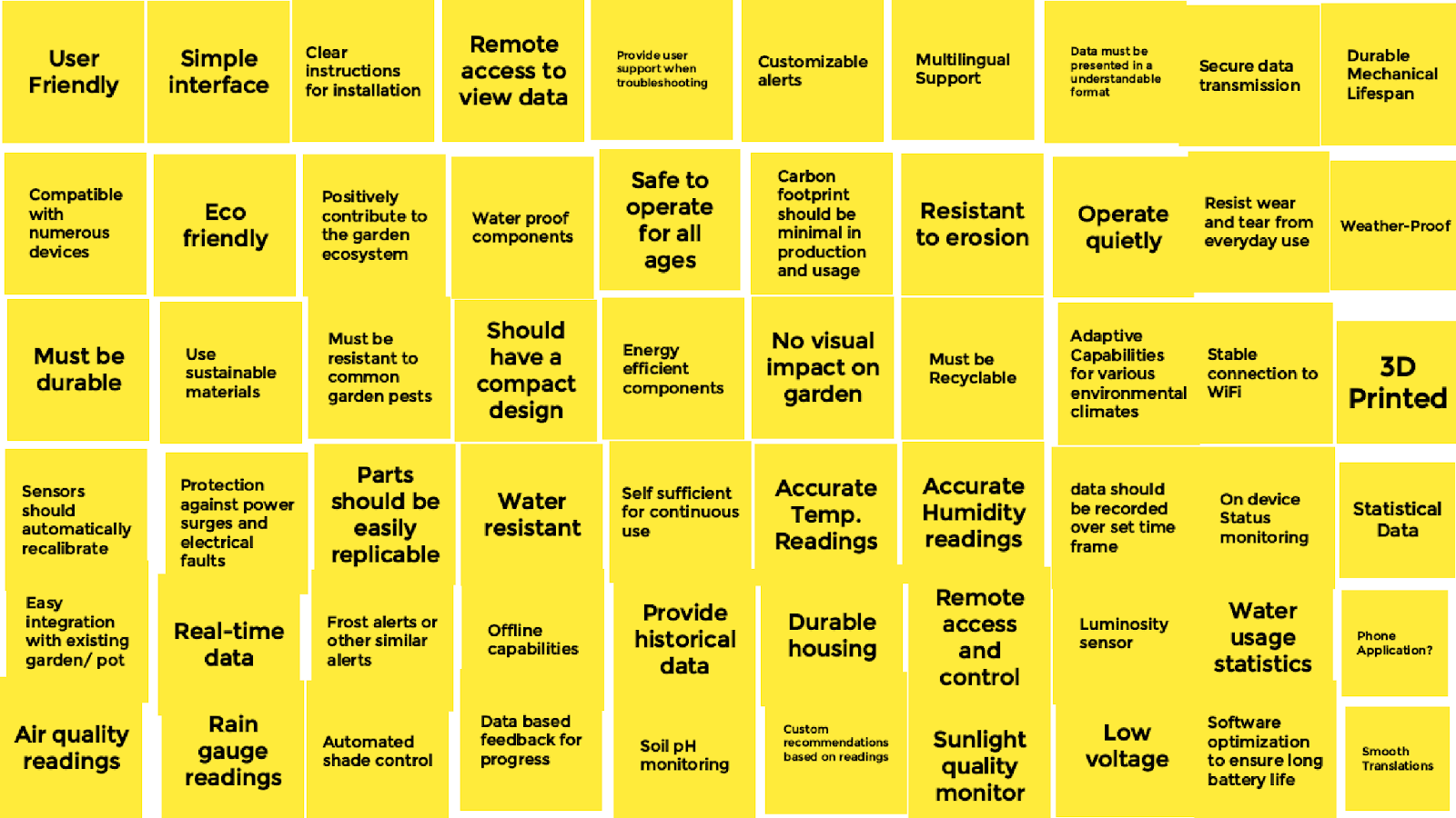
Jamboard Containing 100+ ORGANIZED and UNRANKED User Needs: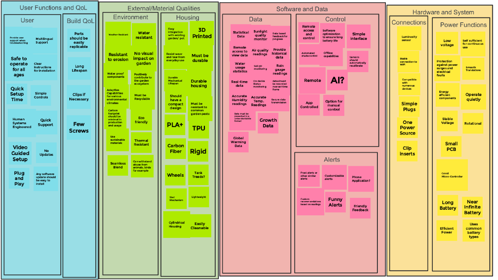
Jamboard Containing 100+ ORGANIZED and RANKED User Needs: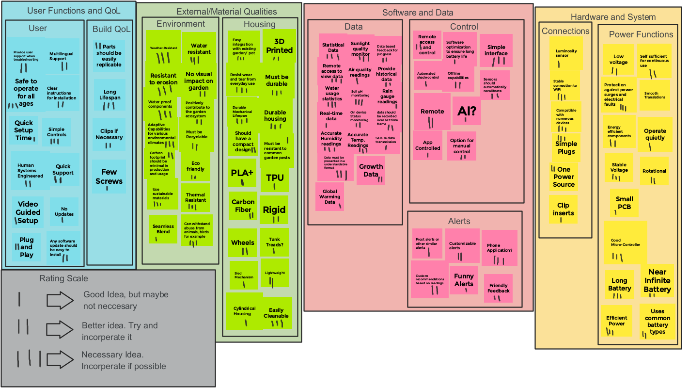
Compiled List of User Needs Based Upon Importance
Items are ranked by order of importance, the top of the table being the most important.
User Functions and Quality of Life
| Direct User Needs | Build Quality of Life Needs |
|---|---|
| Simple Controls | Long Lifespan |
| Safe to operate for all ages | Parts should be easily replicable |
| Multilingual Support | Clips if Necessary |
| Human-Systems-Engineered | Few Screws |
| Clear Instructions | |
| Plug and Play | |
| User support when troubleshooting | |
| Updates should be easy to install | |
| Quick Support | |
| Video Guided Setup | |
| No Updates | |
| Quick Setup Time |
External/Material Qualities
| Environmental Needs | Housing Needs |
|---|---|
| Weather-Resistant | 3D Printed |
| Resistant to Corrosion | Easy Integration with Garden Pot |
| Water-Proof Components | Resist Daily Wear and Tear |
| Adaptive Capabilities for various environmental climates | Must be Durable |
| Carbon footprint should be minimal in production and usage | Durable Housing |
| Use Sustainable materials | Durable Mechanical Design |
| Seamless Blend | Compact Design |
| Thermal Resistant | Resistant to Garden Pests |
| Can withstand abuse from animals, birds for example | PLA+ |
| Eco-Friendly | TPU |
| Recyclable | Carbon Fiber |
| Positively contribute the garden ecosystem | Rigid |
| No visual impact on garden | Should have Wheels |
| Water resistant | Should have Tracks like a Tank |
| Sled-Like Mechanism | |
| Lightweight | |
| Cylindrical Housing | |
| Easily Cleanable |
Software and Data
| Data | Control | Alerts |
|---|---|---|
| Statistical Data | Remote access and control | Frost Alerts |
| Sunlight Quality Sensor | Software optimization for battery life | Custom Alerts |
| Data based feedback for progress | Simple interface | Phone Alerts/Notifications |
| Historical data | Offline capabilities | Funny Alerts |
| Air quality readings | Automated shade control | Friendly Feedback |
| Remote access to view data | Sensor should auto-calibrate | Custom Recommendations based on feedback |
| Water usage stats | AI Controlled | |
| Soil PH monitoring | App Controlled | |
| Rain gauge readings | Manual Control Option | |
| Time-Framed data | Remote Use | |
| On device status | ||
| Real-time data | ||
| Humidity readings | ||
| Accurate temps | ||
| Secure data transmission | ||
| Growth data | ||
| Global warming data | ||
| Understandable formatting |
Hardware and System
| Connections | Power Functions |
|---|---|
| Stable Wifi connections | Protections against power surges and electrical faults |
| Compatible with numerous devices | Stable voltage |
| Simple plugs | Good Micro-controller |
| One power source | Long Battery |
| Clip inserts | Efficient Power |
| Luminosity sensor | Low Voltage |
| Self Sufficient Power | |
| Rotational | |
| Energy Efficient components | |
| Near Infinite Battery Life | |
| Uses Common Battery types | |
| Small PCB | |
| Quietly Operates | |
| Smooth translations |
The rest of our user needs assignment can be found here.
Product Requirements Document
Objectives
The goal for this product is to create a portable weather station that can easily be placed in a home garden. It would be able to track a multitude of different data points including temperature, humidity, soil humidity, and level of light from the sun. The solar panels are capable of tracking the sun’s movement and adjusting the solar panel angle accordingly to get the best power generation possible. This would allow the user to charge and or power any other relevant gardening devices they may have. All data collected will have integration with wifi so the user can see any relevant data, this would allow for easy monitoring and maintenance of their plants. The weather station will be built out of durable materials that can withstand being exposed to the sun for extended periods of time and is durable enough to take abuse from any garden pests that might try to damage it. In the event some component breaks the parts can be easily maintained or swapped out.
Stakeholders
Target group: Garden enthusiasts that are involved with gardening already and want to optimize the growth of their plants. Homeowners with a garden that are interested in maintaining their garden.
Target purchaser: Individual buyers that have a garden at their home, who will purchase this for personal use. Businesses such as nurseries, small farms, and educational institutions that purchase in bulk.
Customer service: To be able to assist customers with installation, troubleshooting, and technical questions about the device. Offer warranty and repair services for defective or malfunction units.
Marketing & Sales division: Target online garden blogs, social media platforms, and online gardening communities. Use retail marketing and partner with garden supply stores or home improvement stores to place our product there.
Senior Management: Ensures product meets market needs and will adhere to company standards. Will decide on long term plans like potential expansions and new partnerships.
Retailers: Will look for the ease of integrating this into the supply chain, looking into the availability of product and delivery time. Make sure this product meets market demand according to their normal customer base that they have.
Regulatory instances: regulatory compliance includes the CE Marking in Europe for safety, health, and environmental protection; adherence to the EU’s 2014/53/EU for radio equipment, 2011/65/EU for the restriction of hazardous materials (RoHS Directive), and 2009/125/EC for energy efficiency and eco-design. In the United States, it complies with FCC Rules part 15 for radio frequency devices and UL safety standards. Canada’s IC standards for electronic equipment are met, along with Russia’s TP TC 020/2011 for low-voltage equipment safety. In Mexico, it adheres to NOM certification for electronic devices, and in Turkey, it complies with AEEE regulations for electrical and electronic equipment. The product meets Japan’s VCCI standards for electromagnetic interference, Singapore’s IMDA certification for telecommunication equipment, and Malaysia’s MCMC approval for communications and multimedia products. Additionally, it complies with Australia’s ACMA standards and New Zealand’s RSM regulations for wireless communications.
Aspects
Product Design
-
The product will be able to easily blend in with any garden environment.
-
The product will be made of light but durable materials.
-
The Product materials will be recyclable.
-
The product will have a distinct appearance to differentiate itself from other similar devices.
-
The product must be easy to maintain any damaged parts.
-
The product should be somewhat customizable based on user preferences or needs.
-
The product will be easy to clean.
-
The product must be able to withstand harsh weather conditions of any kind.
Functionality
-
The product will have an automatically adjusting solar panel for power generation.
-
The product will offer a phone app to relay data collected over wifi.
-
The product can track outside temperature.
-
The product can track air humidity.
-
The product alerts the user when plants need to be tended to based on user set conditions.
Interactivity
-
The product shall be easily set up physically in a garden.
-
The product settings can be adjusted manually on the physical device
Customization
-
The product shall offer multiple case colors the user can pick from.
-
The product has various external ports to allow for easy power distribution to other devices.
Manufacturing
-
The total cost of the product should aim to be around $100.
-
Parts should be easy to mass produce to save on cost.
-
The product shall be designed for minimal to no assembly.
-
The product materials are made static proof to prevent accidental shocks.
-
The product materials should be high quality but as cost effective as possible.
-
The product should be made from recycled materials to save on cost.
Regulations
-
The product shall meet Ingress Protection rating IP65 for water and dust resistance under IEC standard 60529 to ensure functionality in various outdoor conditions.
-
The product shall pass a guided drop test based on IEC 60068 guidelines, including being dropped from a height of 1 meter onto concrete from multiple angles.
-
The product shall pass vibration testing, subjected to frequencies from 10 to 1,000 Hz for one hour in three orthogonal directions.
-
The product shall survive wind resistance testing, ensuring stability in winds up to 60 km/h. 7.5 The product shall comply with electrical safety standards per IEC 62133 for the safety of its LiPo battery.
-
The product shall pass electromagnetic interference (EMI) testing according to IEC 61000 standards to ensure it does not interfere with other electronic devices.
-
The product shall be constructed with recyclable materials where possible and comply with RoHS (Restriction of Hazardous Substances) standards.
-
The product’s solar panel shall pass efficiency tests, maintaining a minimum efficiency rate over its expected lifespan.
-
The product’s sensors (temperature, moisture, etc.) must meet accuracy standards set by ASTM or similar bodies, ensuring reliable data collection.
-
The product shall maintain operational performance in temperatures ranging from -20°C to 50°C.
-
The product shall comply with wireless communication standards (e.g., IEEE 802.11 for WiFi) and not interfere with other wireless networks.
-
The product shall not emit radiation levels exceeding international health standards for electronic devices.
-
The product shall comply with user interface design standards, ensuring accessibility for users with disabilities.
The rest of our user needs document can be found here.
Design Ideation:
In our team, Jeremiah and Jacob laid the groundwork for ideas, while Gavin and Brennan integrated them into our collaborative Jamboard sessions. Our most effective brainstorming involves rapid idea-forming, building upon each other’s contributions. Individual brainstorming was less successful. Our process for organizing and ranking ideas was guided by customer Voice of Customer (VOC) insights. Each team member sketched a design concept: Gavin - Design Concept 3, Jeremiah - Design Concept 2, and Brennan - Design Concept 1. This division of labor resulted in a diverse portfolio of concepts catering to various user preferences.
In the process of generating design ideas, our team adhered to a systematic approach for the effective generation and evaluation of ideas. We commenced the process by employing a digital collaborative tool named Jamboard. Below is a concise overview of the steps we undertook:
-
Jamboard Creation: Our initial step involved the creation of a Jamboard, where team members collaboratively contributed ideas. Through extensive brainstorming sessions, we successfully generated a comprehensive list of 100 diverse concepts.
-
Categorization: To enhance clarity and streamline our ideas, we opted for a different method. We categorized the designs into three distinct bins, each corresponding to a potential design direction. These bins were carefully defined to encapsulate the diverse aspects of User Interaction, Materials, Hardware and Software, Design, as well as Battery/Storage considerations.
-
Concept Sketches: As the third step, we translated our categorized designs into reality by creating three concept sketches/designs using CAD software. This allowed us to obtain a preliminary visualization of how the three designs identified in the categorization stage would manifest in a tangible form.
Below, our team’s Jamboard without categorization can be seen below in Figure 1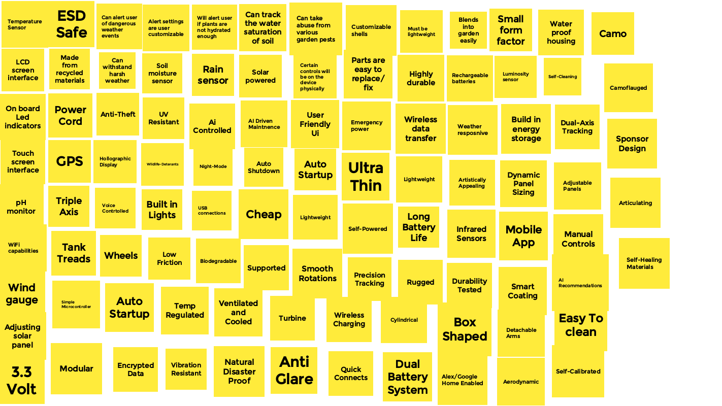
Additionally, our team’s Jamboard with categorization can be seen below in Figure 2
Figure 2: Jamboard Ideation Consisting of 100 categorized ideas

Concept Designs
Following the organization of our Jamboard into distinct “bins” representing potential designs, we took the initiative to bring them to life visually. Consequently, the team crafted three concept sketches, each corresponding to a specific design bin formulated during the Jamboard process.
Design 1
Design 2
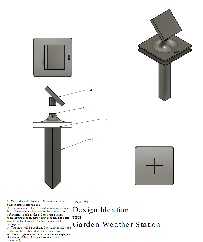
Design 3

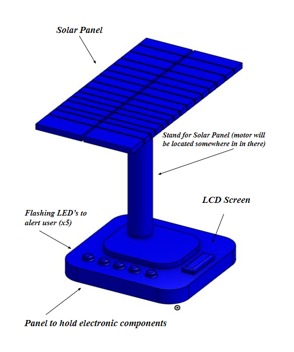
Selected Design:
Block Diagram:
 Each of us are responsible for our own subsystems to make this project come to life. We have a total of four subsystems. These include the micro controller, temperature sensor, humidity sensor, and motor driver. In addition to this we have a solar panel that is not a dedicated subsystem but will be controlled by the motor driver in order to move. The micro controller is the brains of our design and will help us to control everything. The humidity and temperature sensors will gather their relevant data and feed it back to the end user. With all of these parts combined we aim to make a robust garden weather station that will be simple to use while providing valuable information for whoever uses it.
Component Selection:
Component selection is an integral aspect of the engineering design process, as it significantly impacts future design and device development. As a team, we have developed a page dedicated to outlining the components selected for key subsystems, including power management and microcontroller integration, humidity and temperature sensing, and motor driver functionality. Below, you will find the chosen components, along with detailed explanations justifying their selection.
Temperature Sensor
After researching various temperature sensors that we could use we decided on the TC74A4-3.3VCTTR from Microchip Technology. This is a simple temperature sensor that fits our project perfectly.
- It uses the I2C communication protocol to interface with out micro controller which is required for this project.
- Has low power consumption
- Uses 3.3V, this helps our design as are aiming for a very low voltage design
- It has a wide range of temperatures it can capture
All of these factors fit very well into our design and thus we ultimately chose this temperature sensor over other competitors.
Humidity Sensor
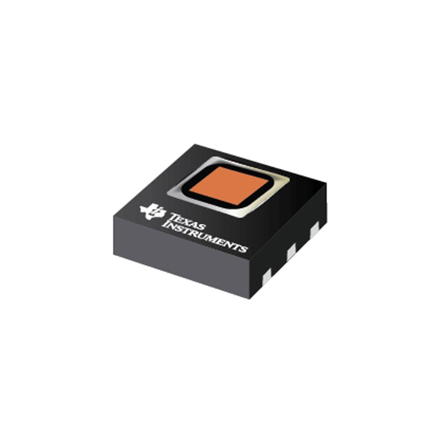
The Texas Instruments HDC1080DMBT is a fantastic humidity sensor that has many benefits that make it a great choice for this project.
- Low power consumption
- Comes calibrated from the factory lending to a great ease of use factor
- Very accurate readings
- Uses I2C
There were a few other options for humidity sensors, but after looking around and weighing various options we decided on this humidity sensor due to its myriad of upsides.
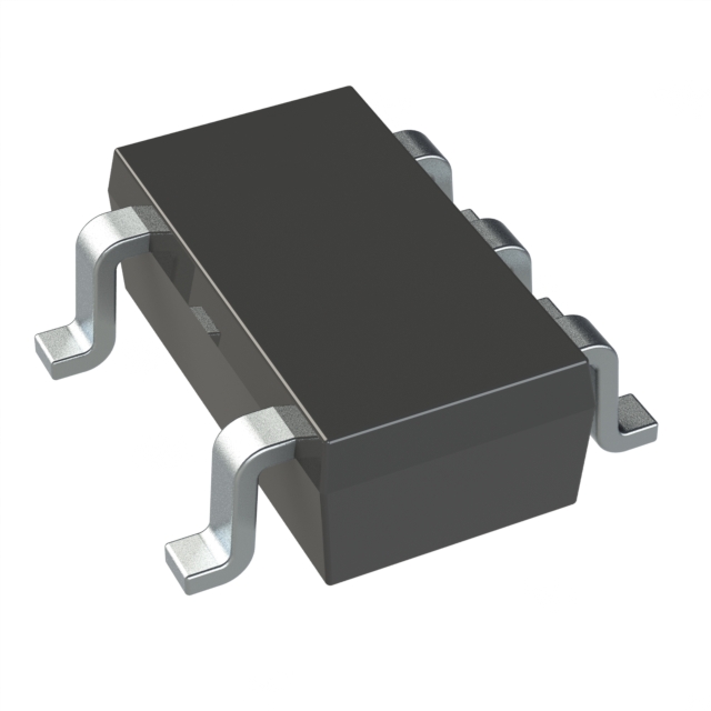
Motor Controller
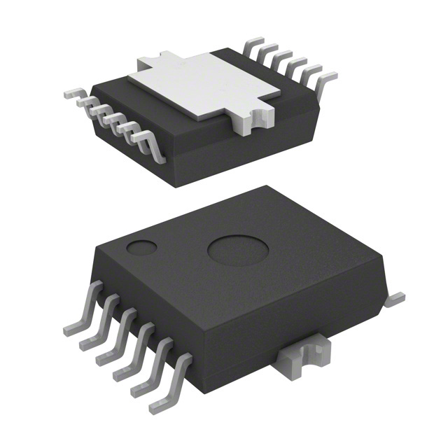
We chose the Infineon Technologies IFX9201SGAUMA1 motor controller as it provides exactly the functionality needed for our design compared to other options. Additionally, we are familiar with the component, as we used it in our Advances Serial Communications assignment. Furthermore, we have example code that can be used to help us, as well as a working schematic.
- Built in H-Bridge allowing for easier control of our motor
- Has built in protection features such as over-current, over-temperature, and under-voltage lockout
- PWM interfaces
- It has a robust design that can handle harsh conditions
- The Advanced Serial Communications Assignment utilized this component, familiarizing us with it.
Battery
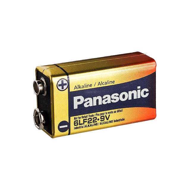
For a battery we opted for a simple household 9V battery and we will be using a switching power regulator in order to get the voltage down to 3.3V to power all of our components. Many of our parts are very low power and our max current going through the system is also low, so a simple battery seemed to the best option.
Switching Power Supply
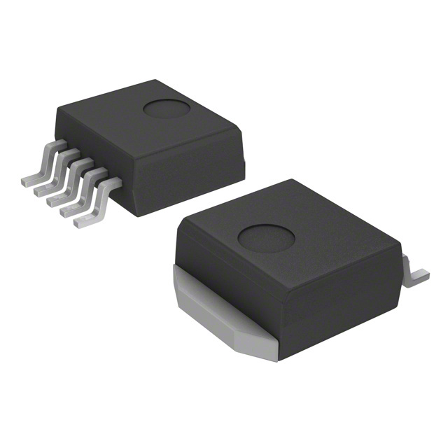
We are using a LM2575-3.3v this component is a simple switcher step-down voltage regulator. With this we will have a fixed output voltage of 3.3V. It can take voltages up to 40V with a 1A load.
Motor
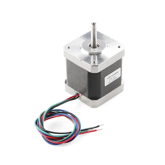
We opted for the simple to use motor ROB-10846 made by SparkFun Electronics. We wanted a robust motor that would also allow for easy control to help drive the movement of our solar panel. This motor is inexpensive but fits all of our design functions that we need.
Solar Panel
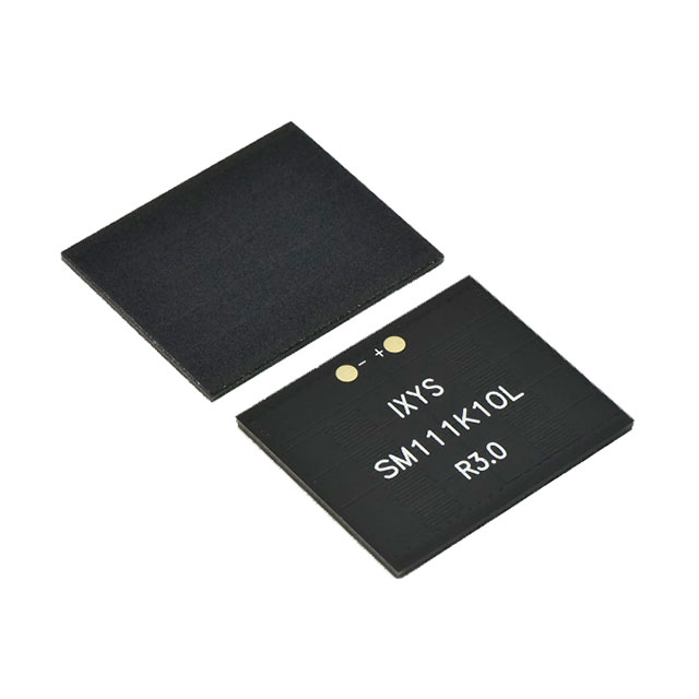
Our onboard solar panel is configured in a diode ORing setup, enabling a split of the load between the 9V system and solar power. This design choice aligns with our commitment to the efficiency. The selected solar panel offers ample voltage for our circuit needs and the potential to support battery charging in future iterations. Most notably, the compactness of these solar cells is a key advantage, perfectly suiting the small form factor we are targeting. This configuration not only optimizes our energy management but also ensures our product remains portable.
Power Budget
For the power budget we took the maximum amperage for each individual subsystem to calculate the power needed for our project. We also are operating at 3.3V which we found that our system will run on the max range of 1201.5 mA. We took the maximum ratings for the subsystems to over compensate and have enough power to run each system.
Microcontroller Selection
| Design Considerations | Team Project-Specific Requirements | Pic Option 1 | Pic Option 2 | Pic Option 3 |
|---|---|---|---|---|
| How many GPIO Pins? | 10 would be preferable | Yes, 35 | Yes, 25 | Yes, 22 |
| Built-in Analog to Digital Converter? How many? | We do not require any | Yes,10 | Yes, 13 | No |
| Built-in Hardware PWM? How many? | We need 1, but more than that would be optimal. | Yes, 5 | Yes, 5 | Yes, 2 |
| Built-in I2C? SPI? How many? | We need 2 | Both, 2 I2c, 4 SPI | Both, 2 | SPI, 1 |
| Built-in UART? How many? | We need 1 | Yes, 2 | Yes, 2 | Yes, 1 |
| Other Required Built-In Features? (optional) | - | - | - | - |
| Additional considerations specific to your project specifications (optional) | - | - | - | - |
| Microcontroller Considerations | Team Project-Specific Requirements | Pic Option 1 | Pic Option 2 | Pic Option 3 |
| Part Number | Include the entire part number (leave off any letters at the end that specify the package type) | PIC18F46K22 | PIC24FJ64GB004 | ATMEGA16U2 |
| Link (URL) to product page | Do not paste links directly into the table. Instead, link them like this. | Digikey | DigiKey | DigiKey |
| Links (URL) to Data Sheets | See #4 | DataSheet | DataSheet | DataSheet |
| Links (URL) to Application Notes | Often provided by manufacturers to give you specific examples of how to use their products. Search for them in the search bar on the Microchip’s website. | Scroll down | Scroll Down | Scroll Down |
| Links (URL) to Code Examples | MicroChip ASC ICC | MicroChip ASC ICC | MicroChip ASC ICC | |
| Links (URL) to External Resources | Search on Google and YouTube for other resources for each specific microcontroller. | MPLAB Tutorial | MPLAB Tutorial | MPLAB Tutorial |
| Production Unit Cost | Find in the Microchip online store, or Digikey | $3.89 | $5.10 | $3.24 |
| Supply Voltage Range | Find in the microcontroller datasheet | 2.3-5.5V | 2.0-3.6V | 2.7-5.5V |
| Absolute Maximum Current for entire IC | Find in the microcontroller datasheet | 200 mA | 200 mA | 200 mA |
| Maximum GPIO Pin Current (Source/Sink) | Find in the microcontroller datasheet | 25 mA | 25 mA | 40 mA |
| 8-bit or 16-bit Architecture | Find in the microcontroller datasheet | 8-bit | 16-bit | 8-bit |
| Available IC Packages / Footprints | Find in the microcontroller datasheet. Choose a microcontroller with both surface mount and DIP/through-hole packages available. See Most Common Mistakes below for requirements to improve manufacturing reliability. | TQFP QFN VQFN UQFN PDIP SSOP SOIC SPDIP |
TQFP QFN SSOP SOIC SPDIP |
TQFP QFN |
| Supports External Interrupts? | Find in the microcontroller datasheet | Yes | Yes | Yes |
| In-System Programming Capability and Type | Allows for programming the microcontroller without removing it from the PCB. Find in the microcontroller datasheet. | Yes, ICSP | Yes, ICSP | Yes, debugWIRE |
| Programming Hardware, Cost, and URL | Find on the microcontroller product page | PiCKit 5 $94.99 | PiCKit 5 $94.99 |
PiCKit 5 $94.99 |
| Works with MPLAB® X Integrated Development Environment (IDE) | Required. See Microchip Development Tools | Yes | Yes | Yes |
| Works with Microchip Code Configurator? | Required. Go to the MCC website, click the “Manual Downloads” tab, scroll to the device library that goes with the PIC you chose (likely “MCC 8-bit PIC”) and read the release notes to make sure your microcontroller is in the list of supported devices. | Yes | Yes | Yes |
| Overall Pros | Write at least 2 for each microcontroller | Has two channels for I2C and SPI Lots of GPIO pins for possible additional features (LCD, etc.) Wide-ranging supply voltage TQFP is the best option as other package sizes (which are bigger) are hard to get a hold of. Similar to the MC’s we have already been using |
Low Power Consumption Lots of ADC channels |
High performance with a low power output/draw Lots of memory, which is good for a complex project like this |
| Overall Cons | Write at least 2 for each microcontroller | Lots of pins, and comes in a TQFP package size, making it hard to solder Lots of unused pins |
Possibly really hard to solder, as it might require baking Possibly too many features creating a steep learning curve |
No I2C Pins Limited Analog features (no ADC) |
| Ranking | 1 = first 2 = second 3 = third |
1 | 2 | 3 |
Final Microcontroller Choice: Option 1: PIC18F46K22
Rationale: This microcontroller meets all of our needs and seems to be the easiest to work with in terms of programming and soldering
Hardware Implementation:

When coming up with this design we had to tackle many different factors. We first needed proper designs for each subsystem and once we confirmed those worked, we had to find a proper MCU to integrate all of our parts into. Once that was achieved we used or MCU data sheet to figure out all the relevant pin assignments that needed to be made for all of our systems. All of this satisfies the user needs for a simple, yet robust, garden weather station that can track various important aspects about any garden that can assist the user in keeping healthy plants. All of our parts combine into a complete package that has a simple set up and ease of use that anyone could pick up, plug in, and start gardening with ease.
You can view our bill of materials here.
Here are some pictures of our PCB design so you can see how the schematic translated into a physical product.
Entire PCB

Front Plane of the PCB

Back Plane of the PCB

Pictures of Final Product


V 2.0 of our Hardware
While we are happy with our overall design, there are still many things to improve and hurdles that we faced that need to ba addressed. Our current design has several potential enhancements that we aim to implement. Initially, we need to address the issues and incompatibilities among existing components. A primary concern involves the humidity sensor—though user-friendly, our chosen sensor, the HDC1080, experiences data transmission problems with the ESP32, an issue discovered post-integration. Therefore, we are prompted to seek a more compatible alternative.
Additionally, the temperature sensor failed to function on our board, leading us to consider more reliable options than those provided in class. Replacing these sensors will not only resolve the functional issues but also enhance the overall system’s usability and debugging process.
To improve functionality further, we plan to integrate a light sensor to control the movement of our solar panels automatically. We aim to optimize the solar panels to power the system effectively, with a battery storage system in place to ensure continuous operation. The battery will take over when the solar panel is not generating sufficient energy, thus maintaining consistent system performance regardless of varying sunlight conditions.
For enhanced diagnostics, we are considering the addition of an LCD or OLED display. This upgrade would allow us to monitor sensor values directly, providing a clear, real-time picture of their operational status, which is a significant step up from the basic debug LED currently used. While the LED serves for rudimentary troubleshooting, a display would offer a much more detailed insight into system performance.
Lastly, we are exploring the possibility of implementing a new motor controller that uses I2C to better integrate with our existing subsystems. Our experiences have indicated that managing components on both SPI and I2C within the same MPLab project can be challenging, which may be attributed to the specific PIC or sensors used.
Moving forward, we will conduct thorough research into more compatible components and rigorously test them together before finalizing Version 2.0 of our project. This comprehensive approach will ensure a seamlessly integrated system in our next MPLab project iteration, achieving greater reliability and functionality.
The code used for the working parts of our project can be found here.
Software Implementation:

Based on our user needs we came up with this basic software diagram to illustrate how we want our project to function. We are trying to simplify our design as much as possible, as a whole it has only a few functions. It will be able to use the solar panel at the top of the device to help charge batteries and or power the system itself. As of right now we will be manually moving the solar panel with a predefined movement pattern that will go on throughout the day and it will reset back to the original position during the night. The on board humidity and temperature sensors will provide the key data our customers need in order to maintain their garden. We will have our sensors give the customer the data after a set amount of time has passed to keep things simple.
When trying to design this we had to think of what we wanted to implement versus what we could implement. If we had more time and could go all out then we would have a light sensor that controls the solar panels, integration of data that could turn on other systems in the garden such as sprinklers for example, but we had to reel in expectations and make a software diagram that not only satisfies our user needs, but to help us make a functioning project. That lead us to where our software diagram is as of right now. A simple, yet robust, program that can help our project to run as we need it to.
Top 5 changes made from software proposal to implementation
- Implementation of On-Board Debugging for Motor Control:
-
Issue: Initially, the motor in our project was not capable of moving forwards and backwards as required. This was a critical functionality flaw.
-
Resolution: We decided to utilize the on-board debugging LED to indicate a reverse signal. This involved modifying the motor control code to integrate reverse functionality and using the LED as a visual indicator for debugging and status checking.
-
- Modification of Temperature and Humidity Sensor Outputs:
-
Issue: The temperature and humidity sensors were not transmitting data correctly to the MQTT server, which was crucial for remote monitoring.
-
Resolution: The team pivoted to send an example data packet to the MQTT server, mimicking what the actual sensor data should look like. This allowed us to isolate the issue to sensor configuration rather than communication.
-
-
Separation of Sensor and Motor Controls onto Different Boards:
-
Issue: Integrating the temperature sensor, humidity sensor, and motor on a single board caused conflicts within the MCC (Microchip Code Configuration) settings, leading to operational failures.
-
Resolution: To overcome this, we deployed two separate boards for demonstration purposes. One board handles the sensors, and the other controls the motor, ensuring that MCC configuration issues are avoided and each function operates reliably.
-
-
Motor does not move using data input:
-
Issue: Motor does not move as it is stated on our software diagram. We could not get the motor to move by using another subsystem or data input.
-
Resolution: We instead had to make the motor move on a preset path and rotation amount in order to get it functioning in general.
-
-
Need a way to debug our code and parts
- Issue: in our software diagram we did not specify how we would debug any of our subsystems when issues were to eventually arise.
- Resolution: We added some very basic LED light control code to various parts to see what was and was not working on our board.
V 2.0 of our Software
In the envisioned Version 2.0 of our software design, we aim to make substantial enhancements that optimize functionality and enhance system robustness. One significant upgrade involves the integration of environmental triggers; specifically, implementing an interrupt-driven system where reaching certain humidity or temperature thresholds automatically activates a misting system. This improvement allows for real-time environmental responsiveness and efficient system operation.
Additionally, we plan to introduce working motor code to enable the solar panel to dynamically track the sun, maximizing energy absorption throughout the day. This adaptive positioning is crucial for boosting the system’s overall energy efficiency.
Further enhancements include refining the MQTT server integration, particularly improving how the system handles data transmission from new humidity and temperature sensors. Optimizing code for reliable and timely data communication is essential for effective system monitoring and management.
To enhance system usability and adaptability, we will incorporate a time-based interrupt for automated adjustments, such as repositioning the solar panel at sunset to protect mechanical components. Moreover, an interrupt that allows users to request and receive data instantly will be added, enhancing user interaction by providing immediate feedback and system status.
The software will be divided into several key modules: an Environmental Monitoring Module for handling sensor operations, an Energy Management Module for controlling solar panel orientation, a Communication Module for managing MQTT server interactions, and a User Interface Module for real-time data presentation and user input handling.
To improve debuggability and reliability, we plan to integrate advanced logging and diagnostic capabilities to monitor system performance and swiftly pinpoint issues. Enhanced exception handling will ensure robust error management and system stability.
Overall, these improvements will not only simplify protocol design but also significantly increase the system’s reliability, functionality, and user-friendliness. By aligning with technological trends and laying a foundation for future enhancements, this approach ensures that our system remains scalable and sustainable.
System Verification Matrix
Here is our final system verification matrix showing all the parts we were able to get connected to each other properly

Lessons Learned
Throughout the course of our project, our team gained invaluable insights that enriched our understanding of many facets of being an engineer. From design, research, planning, budgeting, debugging, testing, and many more. One of the most crucial lessons was the significance of a visually appealing exterior design, which we found to substantially increase the overall success of the project by attracting more interest and instilling a sense of quality. We also learned the importance of thorough research on components; for instance, discovering that our motor controller required two different voltage inputs was a pivotal detail that could have led to critical issues if overlooked.
Another notable discovery was the efficiency of solder paste in our processes. It reduced the physical stress on our team during soldering and enhanced the neatness and functionality of the printed circuit boards. Similarly, the use of 3D printing was transformative for our prototyping and design evaluation, allowing for quick iterations and precise mock-ups which facilitated better design decisions.
Our project’s larger-than-anticipated budget opened up possibilities for incorporating more innovative designs and components, teaching us the importance of budget flexibility. This project also highlighted the value of adaptability; when faced with unforeseen challenges, our ability to pivot and try new approaches kept the project moving forward.
We honed our skills in efficient product research, which proved pivotal in ensuring that our prototype was innovative and functional. The effective use of AI tools assisted with code debugging and generated many ideas for design and component selection, which significantly streamlined our development process. Additionally, mastering GitHub allowed us to create a visually appealing website that effectively demonstrated our product and its capabilities.
Feedback from our design review also played a critical role. Suggestions such as offering the product in different colors and using ASA plastic for UV and outdoor protection guided our next steps in product development. These insights, drawn from both hands-on experiences and constructive feedback, have profoundly shaped our approach to project management and execution, underscoring the importance of aesthetics, technical precision, and ability to adapt in achieving a successful project outcome.
Recommendations for Future Students
With everything we have learned throughout this course we hope to help any other future students in this class with a small list of advice that helped us in our success of this course.
-
Stay on top of all of the ICC assignments so you don’t fall behind.
-
Try and invest in some extra breadboards to save your circuits, as they can be used in the following weeks homework or in-class checkoffs.
-
Keep track of your files for all the assignments by using a designated folder or drive, with a specific naming convention.
-
Do your research on what potential microcontrollers require, as well as what functions they do. Specifically, find out how many I2C and SPI channels it has, how it can be programmed, and look into some of the potential pitfalls/issues that are known to the microcontroller.
-
Do your research on the circuits and components you decide to use. The components used for the ICC’s are the best case to use, as you already have the circuit and working code and knowledge.